Saturday, August 1, 2009

lincoln ls, clockspring removal

clock spring air bag

Complete Clock Spring Replacement (PICS)


I took the time to get the entire process in pictures complete with exact
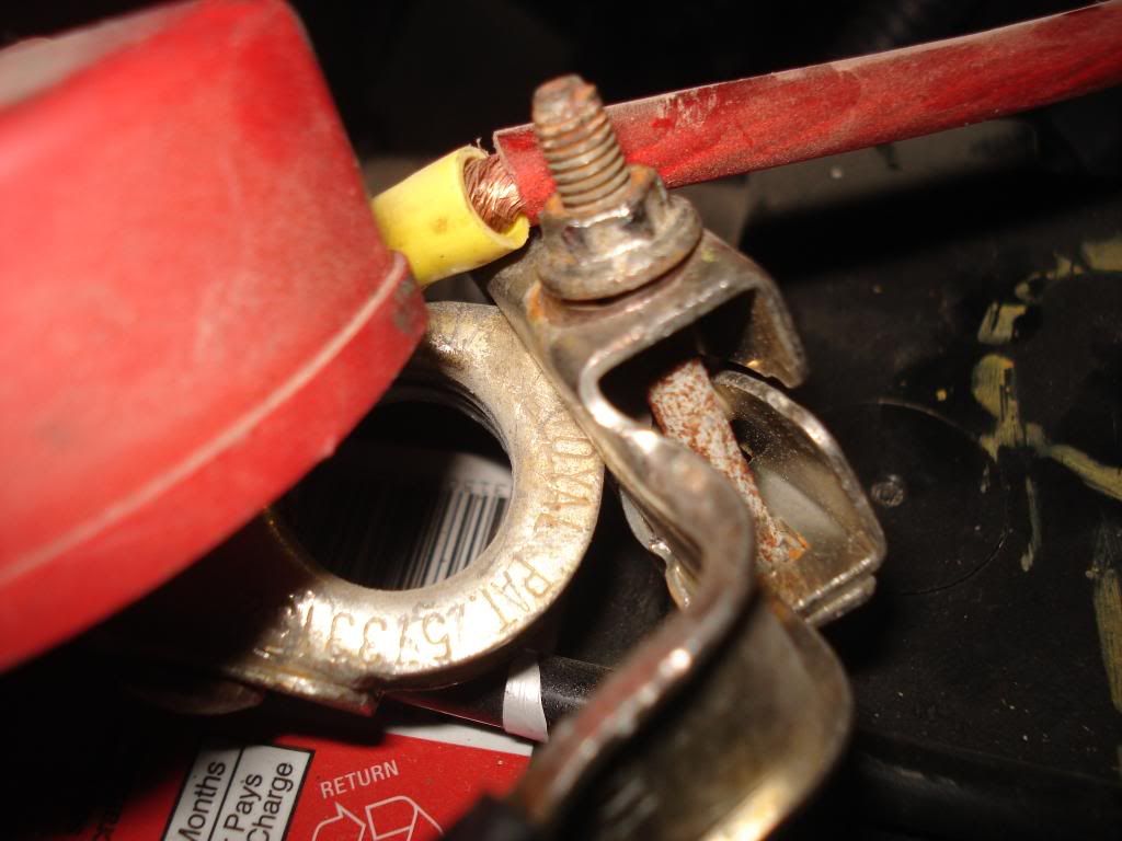
tools. First and foremost, make sure the battery is disconnected. Attach the
two battery cables together. It helps to drain any residual voltage in the car
and prevent any accidental connections with the battery terminals.


small flat head screwdriver

Phillips #2 screwdriver

Rachet with 7,8,13 mm sockets and a 3-4" extension

2 torx bit sockets T25 and T50

Differential Bearing Puller vvv These guys vvv


You are also going to need the proper socket to turn the bolt on the pullers.


Ok tools gathered, and battery voltage gone, lets start working.


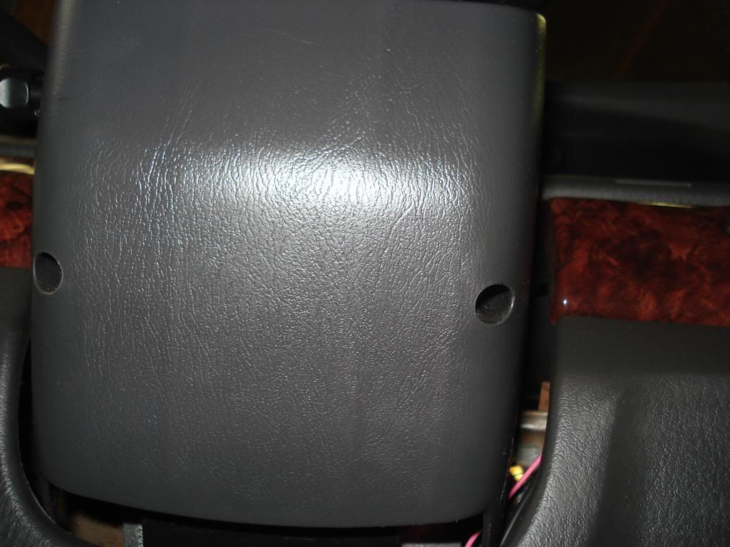
1) Remove two plugs on steering wheel back cover. They might be a bit of a
pain, but a small flat head can do it, just be patient.


2) Using the 8mm socket, remove the two air bag retaining bolts from behind
the plugs. The air bag module should start to slide out on its own. You can
pull it off the steering wheel, but dont yank on it. There is still the air
bag connector which needs to be removed.


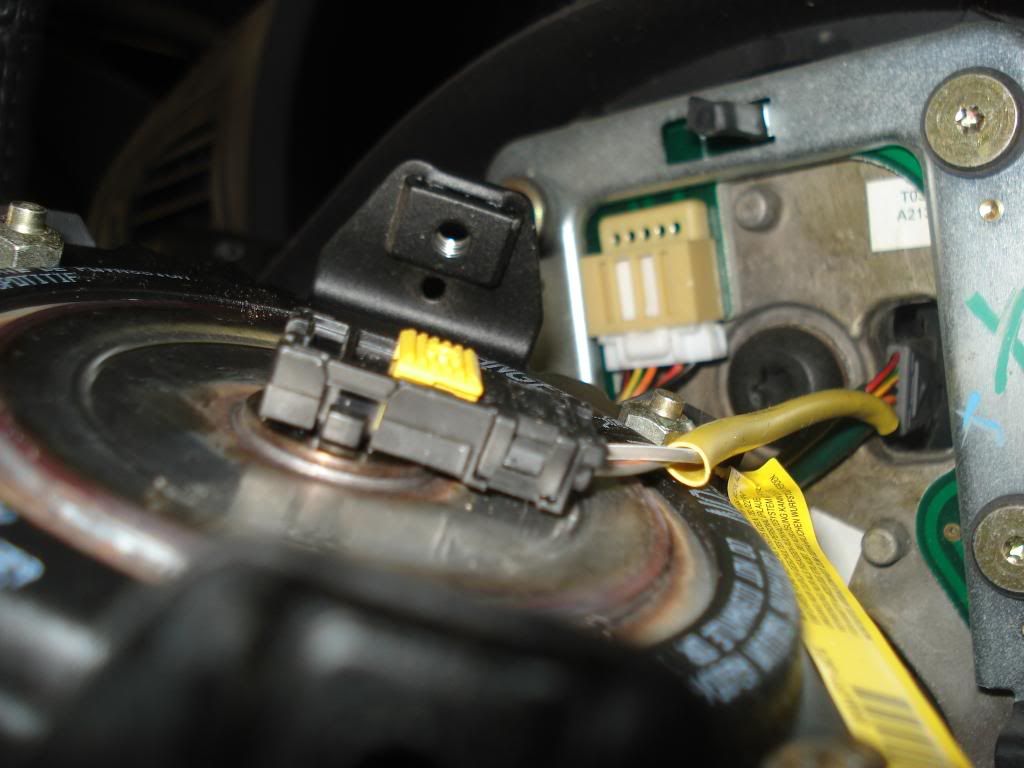
3) Slide the yellow tab towards back towards the wires and sqeeze the two
small black square tabs into the clip. I used both hands since they are so
small. When the clips are pushed together the connector can be pulled straight
back away from the module. Once off, you can go put the air bag somewhere
safe, remember to keep the Lincoln Star facing up


4) Remove the push pins from the bottom of the dash front, then pull of the
cover enough to disconnect the wires for the trunk release and fuel door.


5) Using the 7mm socket, remove the two screws holding the hood release in
place (i used a nut driver with the socket on it but the ratchet will work
perfectly)


6) Using the flat head screw driver (pliers would work well too) pry the two
push pins from the instrument insulator panel. Pull the panel most of the way
out, then remove the light by twisting counter clock wise.


7) Remove the 8mm screw holding the heater duct in place, then pull the heater
duct towards the drivers door and out.


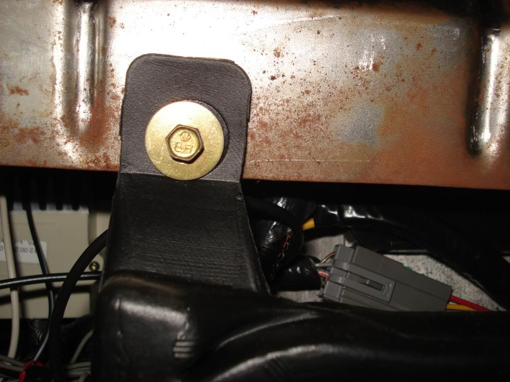
8) This step is in the Ford instructions, but I dont know the reasoning. I did
it, but I think it doesnt make a difference either way. Just under the center
console speaker is two 13mm bolts. Loosen but dont remove them cause they
arent fun to line back up in the holes. You will need to pull the carpet back
to access these bolts.


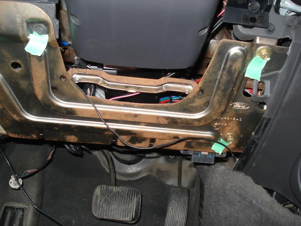
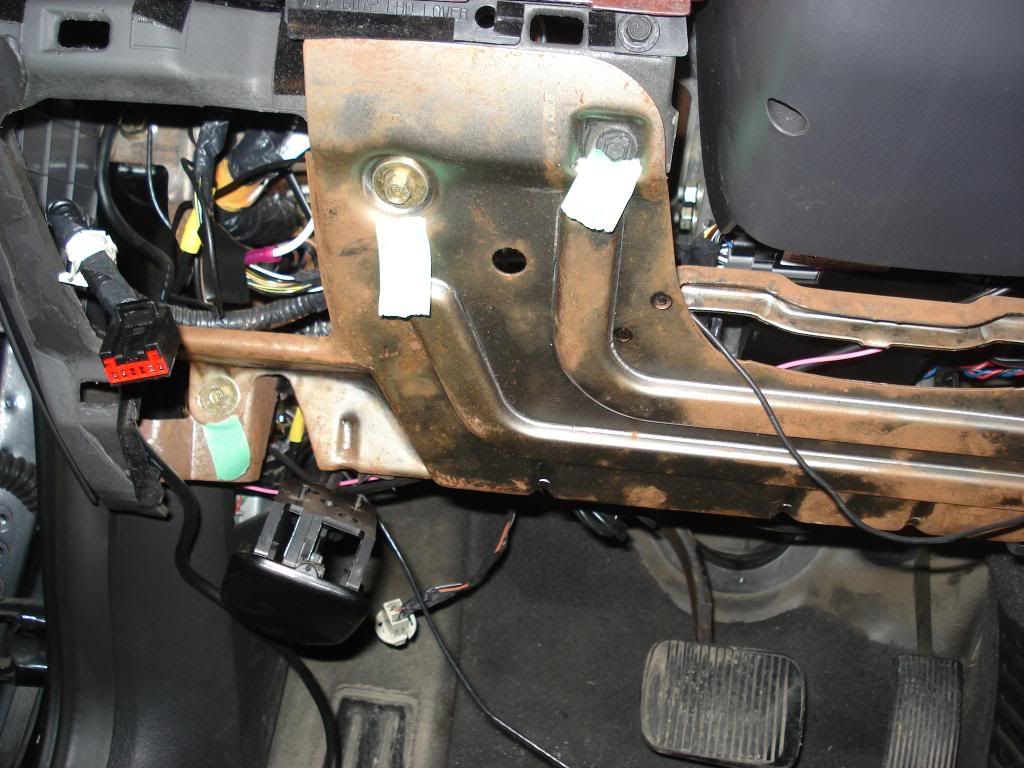
9) Remove the 5 screws in the steering column opening reinforcement panel.
Four of them are 8mm, and the one just to left of the steering column is 7mm.


OK, we are moving along nicely. Before you get any further make sure your
front wheels are straight and the steering wheel is centered. This is
important and without it the clock spring may not line up correctly.


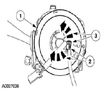
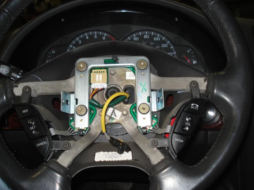
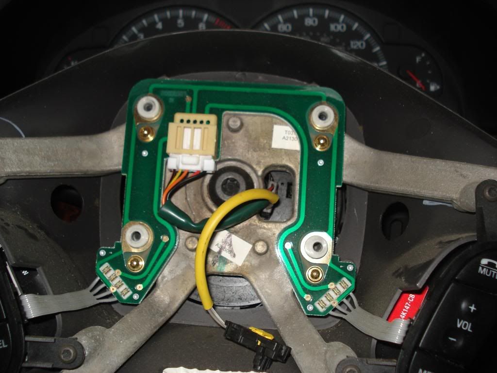
10) There is four T25 torx screws in the steering wheel holding the horn
actuator on. Remove those bolts, but be careful, there is a spring behind each
one. Dont lose them. Gently move the green circuit card down and out of the
way. You can unplug the wires if you want, but its not neeed and the plugs are
pretty small. The big white connector in the center of the circuit board does
need to be removed.


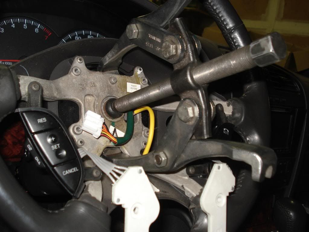
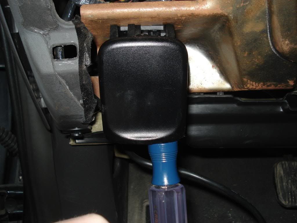
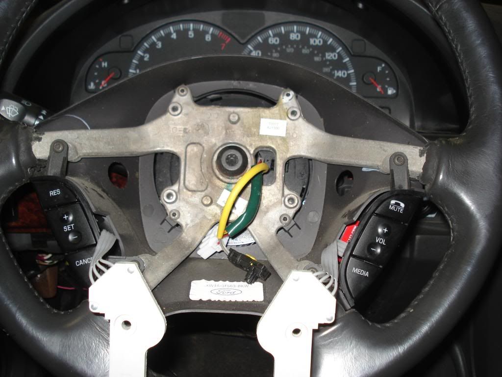
11) Remove the steering wheel by first using the T50 torx socket to remove the
center bolt. It may be easier to have someone hold the steering wheel while
you break it free, but I got it free myself so a helper isnt necessary. Then
install the fingers of the bearing puller on the top and bottom of the
steering wheel frame. The center bolt on the puller should line up and fit
right where torx bolt went. If it does, then tighten the bolt down until the
steering wheel pops free. If it doesnt, then thread the torx back in a few
turns and center the puller bolt on it. Its more of a pain since the torx bit
will spin with the puller bolt. I only have a picture of the pullers on the
torx bolt, but i took it out before cranking down on the puller bolt.


12) Remove the two screws in the bottom of the steering column with a #2
phillips screwdriver, and pull down on the bottom part of the column. There
are plastic clips inside there, but I just pulled and it came free.


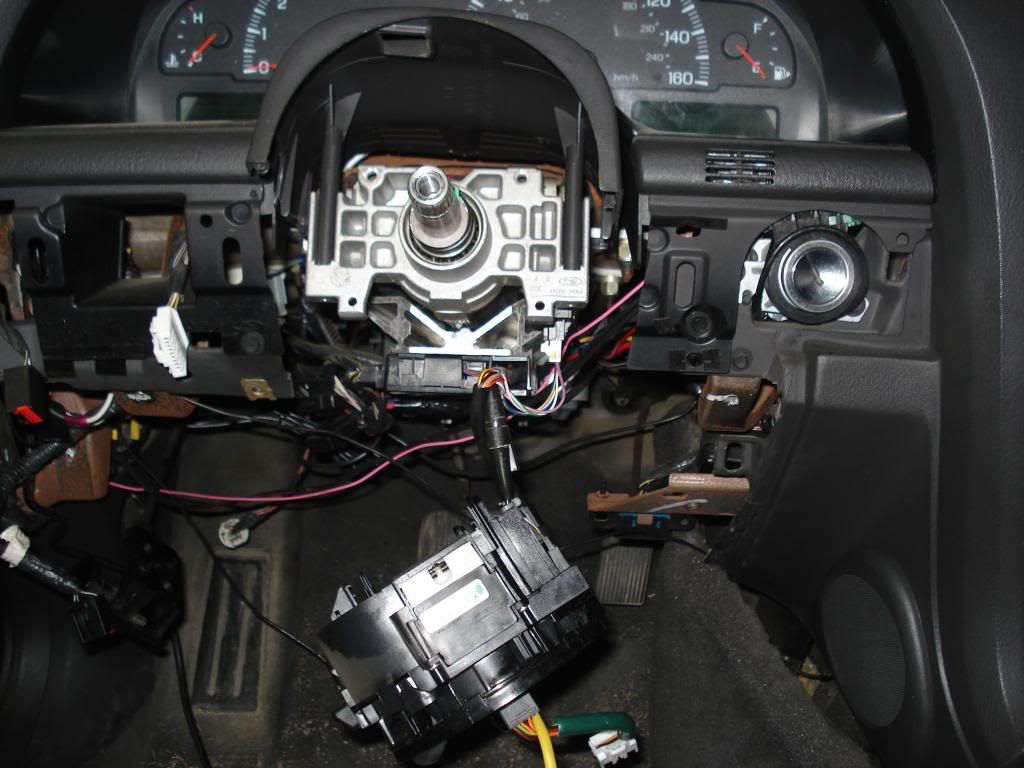
By now you should have clear access to the clock spring and all the
connectors. Everything is done by hand from her out.


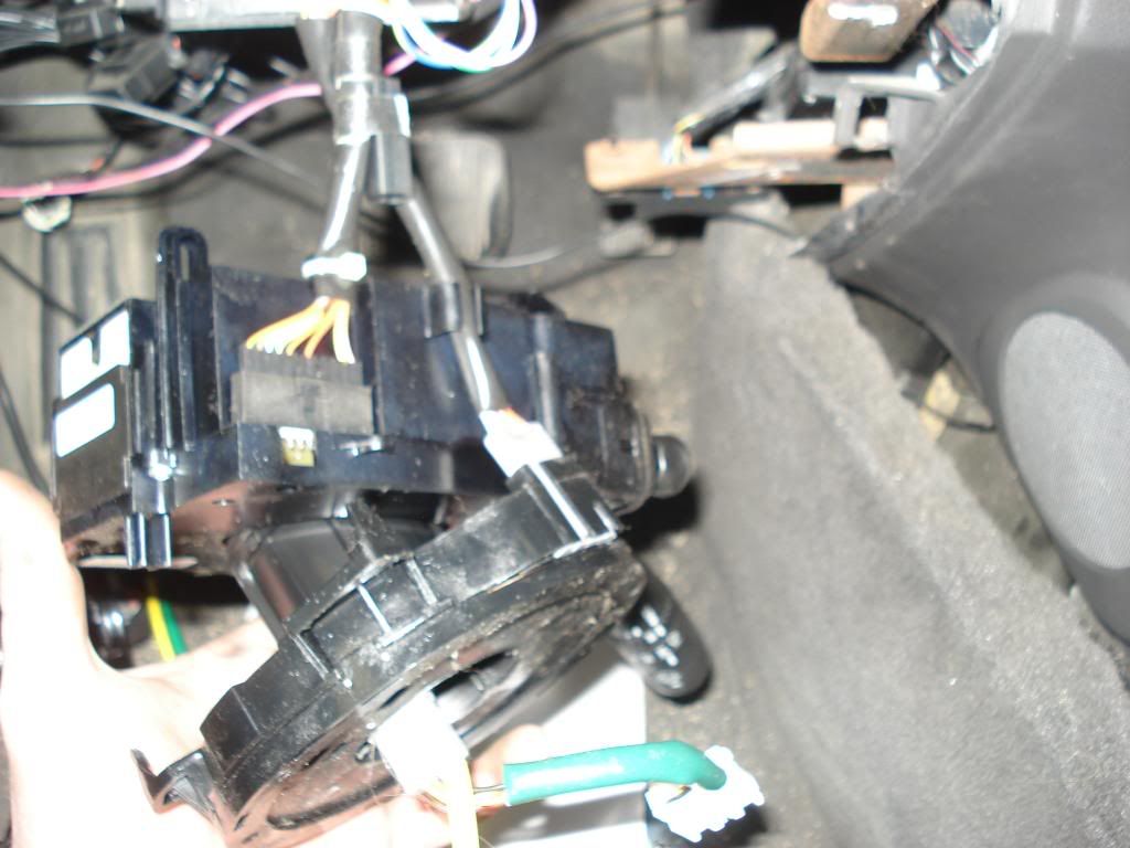
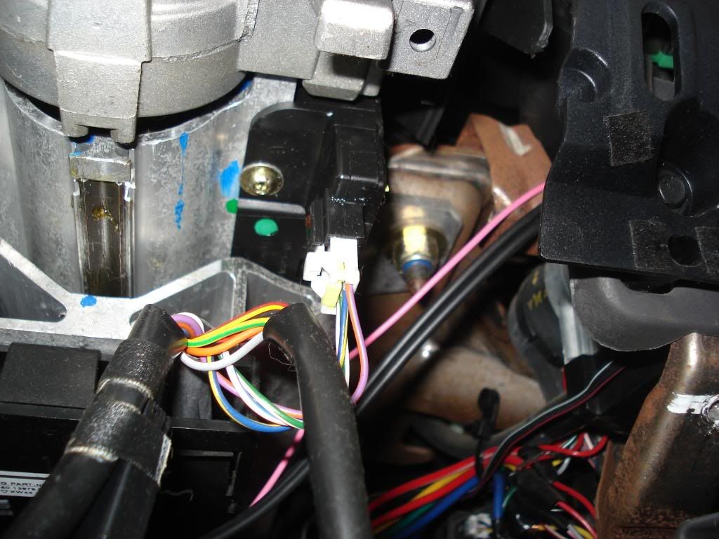
13) There are four clips holding the clock spring cylinder to the steering
wheel controls such as the wiper controls. First pull the two boxes straight
towards you and off the steering shaft. Then with your fingers (or a
screwdriver) pry the clips free so the clock spring comes free.


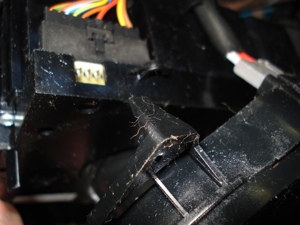
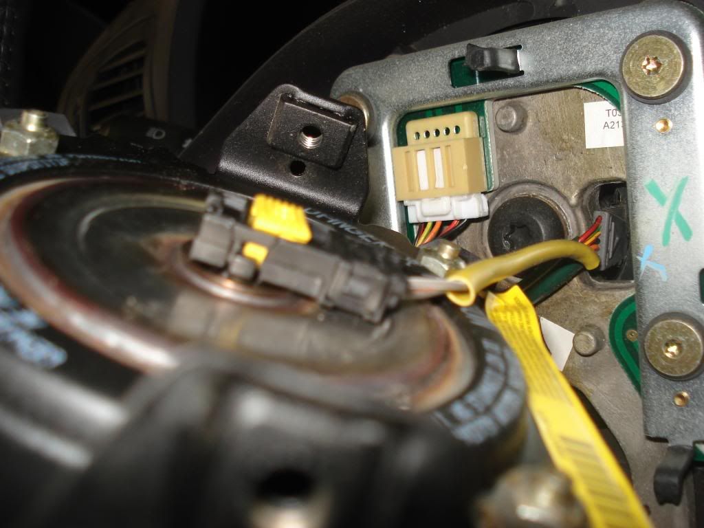
14) Remove all the connectors that go to/from the clock spring box (dont worry
about the wires on the cylinder)


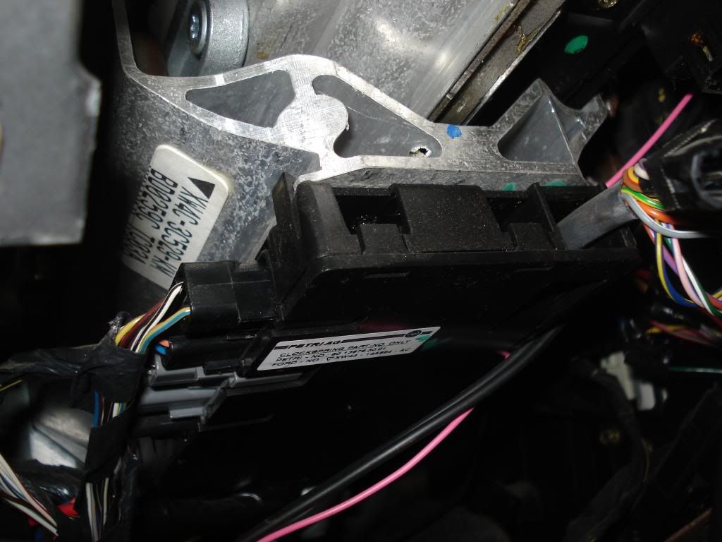
cut the white wire tie in this picture to remove the long flat connector


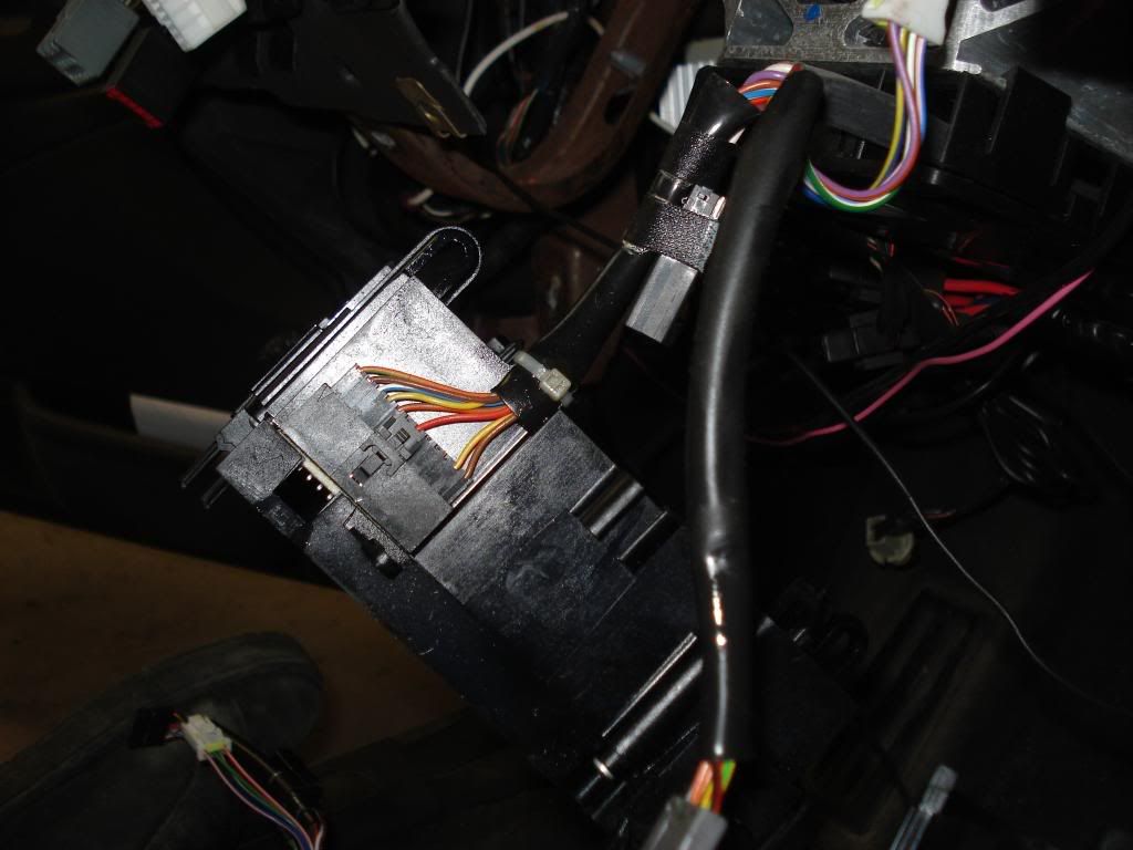
15) Now you just have the four clips on the corners of the clock spring
holding it to the dash. Get the top two off and the bottom two will follow.


Ok, now the removal procedure is done. The new clock spring will have a
plastic key to keep it from rotating on you. Reverse the removal procedures
but wait until the clock spring cylinder is on the steering column before
pulling it off.

Sunday, July 5, 2009

06 lincoln ls v8 engine parts and discription images


SECTION 303-01: Engine


2006 Lincoln LS Workshop Manual


IN-VEHICLE REPAIR


Procedure revision date: 06/24/2005


Intake Manifold


Material
ItemSpecification
Motorcraft Metal Surface Cleaner

ZC-21
WSE-M5B392-A


ItemPart NumberDescription
114A464Throttle position (TP) sensor electrical connector (part of 12B637)
214A464Fuel pressure sensor electrical connector (part of 12B637)
314A464Throttle body electrical connector (part of 12B637)
49D289Evaporative emissions (EVAP) hose
514A464Fuel rail temperature sensor electrical connector (part of 12B637)


ItemPart NumberDescription
69E499Fuel pressure sensor vacuum connector
79E498Exhaust gas recirculation (EGR) system module vacuum connectors
814A464EGR system module electrical connector (part of 12B637)
99D477EGR system module-to-exhaust manifold tube fitting


ItemPart NumberDescription
10W520411RH engine appearance cover bracket nuts (2 required)
11129723RH engine appearance cover bracket
12W520411LH engine appearance cover bracket nuts (2 required)
13129723LH engine appearance cover bracket


ItemPart NumberDescription
14W704916Intake manifold bolt (7 required)
15W708238Intake manifold stud (3 required)
169424Intake manifold
179439Intake manifold gasket (2 required)

Removal


WARNING:
Do not smoke or carry lighted tobacco or open flame of any type when working on
or near any fuel-related component. Highly flammable mixtures are always present
and may be ignited, resulting in possible personal injury. Failure to follow
these instructions may result in personal injury.


WARNING:
Fuel in the fuel system remains under high pressure even when the engine is not
running. Before repairing or disconnecting any of the fuel system components,
the fuel system pressure must be relieved to prevent accidental spraying of
fuel, causing personal injury or a fire hazard. Failure to follow these
instructions may result in personal injury.


  1. Release the fuel system pressure. For additional information, refer to Section
    310-00
    .


  1. Drain the cooling system. For additional information, refer to Section
    303-03
    .


  1. Disconnect the battery ground cable. For additional information, refer to Section
    414-01
    .


  1. CAUTION:
    The engine appearance cover is equipped with a noise suppressor. If the
    noise suppressor becomes separated from the engine appearance cover it must
    be positioned on the intake manifold prior to installing the engine
    appearance cover.


    Remove the engine appearance cover and the noise suppressor (if detached).


  1. Remove the air cleaner outlet pipe. For additional information, refer to Section
    303-12
    .


  1. Remove the cowl panel grille. For additional information, refer to Section
    501-02
    .


  1. Disconnect the fuel supply tube spring lock coupling from the fuel rail.
    For additional information, refer to Section
    310-00
    .


  1. Remove the 6 bolts and the cross-vehicle brace.


  1. Disconnect the throttle position (TP) sensor electrical connector.


  1. Disconnect the fuel pressure sensor electrical connector and vacuum hose.


  1. Disconnect the throttle body electrical connector.


  1. Disconnect the evaporative emissions (EVAP) hose from the intake manifold.


  1. Disconnect the fuel rail temperature sensor electrical connector.


  1. Disconnect the exhaust gas recirculation (EGR) system module electrical
    connector and the vacuum harness from the EGR system module.


  1. Disconnect the EGR system module-to-exhaust manifold tube from the EGR
    system module.


  1. Remove the crankcase ventilation tube.


  1. Disconnect the vacuum supply tube.


  1. Detach the vacuum harness retainers from the LH engine appearance cover
    bracket.


  1. Detach the engine wiring harness from the engine appearance cover
    brackets.


  1. Remove the 4 nuts and the 2 engine appearance cover brackets.


  1. Disconnect the 8 fuel injectors and the radio interference ignition
    capacitor electrical connectors.


  1. Remove the 2 nuts and the engine wiring harness retainer.


  1. Remove the nut and the radio interference ignition capacitor.


  1. Disconnect the 2 throttle body coolant tubes.


  1. NOTE: The throttle body and adapter are shown removed for clarity.
    It is not necessary to remove the throttle body and adapter to remove the
    intake manifold.


    Remove the 7 bolts and 3 studs in the sequence shown.


  1. Remove the intake manifold and discard the gaskets.


Installation


  1. CAUTION:
    Do not use metal scrapers, wire brushes, power abrasive discs or other
    abrasive means to clean the sealing surfaces. These tools cause scratches
    and gouges, which make leak paths. Use a plastic scraping tool to clean the
    surfaces.


    Clean the gasket sealing surfaces.


  1. Install new gaskets, the intake manifold, the 7 bolts and the 3 studs in
    the sequence shown.

    • Tighten to 20 Nm (15 lb-ft).


  1. Connect the 2 throttle body coolant tubes.


  1. Install the radio interference ignition capacitors and nuts.

    • Tighten to 10 Nm (89 lb-in).


  1. Install the engine wiring harness retainer and the 2 nuts.

    • Tighten to 10 Nm (89 lb-in).


  1. Connect the 8 fuel injectors and the radio interference ignition capacitor
    electrical connectors.


  1. Install the 2 engine appearance cover brackets and the 4 nuts.

    • Tighten to 6 Nm (53 lb-in).


  1. Attach the engine wiring harness to the engine appearance cover brackets.


  1. Attach the vacuum harness retainers to the LH engine appearance cover
    bracket.


  1. Connect the vacuum supply tube.


  1. Install the crankcase ventilation tube.


  1. Connect the EGR system module-to-exhaust manifold tube to the EGR system
    module.

    • Tighten to 40 Nm (30 lb-ft).


  1. Connect the EGR system module electrical connector and the vacuum harness
    to the EGR system module.


  1. Connect the fuel rail temperature sensor electrical connector.


  1. Connect the EVAP hose to the intake manifold.


  1. Connect the throttle body electrical connector.


  1. Connect the fuel pressure sensor electrical connector and vacuum hose.


  1. Connect the TP sensor electrical connector.


  1. Install the 6 bolts and the cross-vehicle brace.

    • Tighten to 20 Nm (15 lb-ft).


  1. Connect the fuel supply tube spring lock coupling to the fuel rail. For
    additional information, refer to Section
    310-00
    .


  1. Install the cowl panel grille. For additional information, refer to Section
    501-02
    .


  1. Install the air cleaner outlet pipe. For additional information, refer to Section
    303-12
    .


  1. CAUTION:
    The engine appearance cover is equipped with a noise suppressor. If the
    noise suppressor becomes separated from the engine appearance cover it must
    be positioned on the intake manifold prior to installing the engine
    appearance cover.


    Install the noise suppressor (if detached) and the engine appearance cover.


  1. Connect the battery ground cable. For additional information, refer to Section
    414-01
    .


  1. Fill and bleed the cooling system. For additional information, refer to Section
    303-03
    .


Tuesday, May 19, 2009

automatic transmission disassembly - 5R55S

Lincoln LS Workshop Manual Information
Automatic Transmission — 5R55S